|
|
|
|
|

|
|
|
Hagelin TC-52 (Telecrypto)
|
 |
|
|
Hybrid on-line cipher machine
The TC-52 was an on-line cipher machine for teletype-based communication
systems (Telex), developed by Crypto AG (Hagelin) in Zug (Switzerland) between 1954 and 1955 [1].
It was an improved version of the earlier T-52
machine (1951-1952) and was a hybrid between a wheel-based mechanical cipher
machine (basically an M-209
or C-38)
and a mixer machine. Both machines were based on
Telekrypto-Gerät 35,
a cipher machine that was co-developed with
Dr. Edgar Gretener (Gretag)
between 1949 and 1951 for use with
14-bit ETK-47 teleprinters.
|
Like the T-52, the TC-52 was intended for on-line encryption of 5-bit (baudot)
teleprinter signals (telex). As such, the mechanics of the machine had to
be fast enough to keep up with the common telex speed of approx. 50 baud.
For secure data exchange, the TC-52 had two paper tape
readers on top of its body. One reader would contain the clear text,
whilst the other one contained the cipher tape.
When the cipher tape was a truely randomly created data stream,
the cipher would be unbreakable, as the key tape acts as a
One-Time Pad (OTP).
|
|
|
Such systems are commonly called
mixer machines
or One Time Tape (OTT) systems,
and are all based on the Vernam Cipher.
The cipher stream is 'mixed' with the clear text stream by
means of a digital XOR operation (modulo-2 addition).
The resulting stream is then sent to the other end via telephone
lines or by radio.
By applying the same cipher stream again at the other end, the
original clear text is revealed.
Unlike many other OTT systems however, the TC-52 also contained a
standard Hagelin mechanical wheel-based cipher machine that was
converted for on-line encryption of the electric data signals.
This additional cipher machine was based on the
M209 that was also used by the American Army
during WWII.
It could be used as a fall-back method in case no OTT was available
for the mixer machine.
|
|
|
|
|
|
|
As mentioned in the introduction on this page, the TC-52 is in fact a
combination of two cipher machines in one case. In theory, it is 'just' a
mixer machine that works according to the Vernam Cipher
principle. The letters of the cleartext message are 'mixed' with the
contents of a paper tape that contains fully random symbols.
With the right precoutions, this cipher is unbreakable.
This situation is given in the simplified block diagram below.

| |
|
Simplified block diagram of the TC-52 in transmit-mode
|
If no random key tape is available, it is possible to 'fall back' to a
less secure pseudo-random key generator, based on a mechanical Hagelin
cipher machine, similar to the M-209 (bottom right).
The mechanical movements of the wheel based M-209 pin/lug machine,
is converted into a 5-bit digital code, similar to that generated by
the tape reader.
On the input side, the user can choose between typing the text directly
on the teletype (on-line) or sending a previously prepaired paper tape
(off-line). The latter is more secure as it avoids making mistakes and
does not reveal the typing habits of the operator (Traffic Analysis).
|
Contrary to the earlier T-52,
The TC-52 can be used for the transmission of both on-line messages and
messages that have been prepaired off-line. When used as an on-line
ciphering machine, a teletype machine (Telex) is connected directly to
the TC-52. When in transmission mode (TX), the message is typed on the
teleprinter and the TC-52 will process the data, encipher it and
transmit it on the line.
|
In off-line mode, the the message is first prepared on a (separate)
teletype machine and stored on a punched paper tape. The pre-recorded
message is then entered into the rightmost tape reader on top of the
TC-52, after which the user presses the Start button.
The image on the right shows the two tape readers.
The rightmost one is used for the plaintext tape.
The leftmost one was used for the OTT key tape.
Off-line operation was not possible with the earlier T-52
as it lacked the rightmost tape reader.
|
|
|
The image above reveals that this machine was probably used in Denmark,
as the text below the two tape reader is in Danish. The text label is bolted
onto the cover of the machine with 6 tiny little screws, allowing the machine
to be adapted for different countries.
Removing the text label reveals the original French text,
as can be seen in image #5 below.
|
Removing the top lid of the TC-52 reveals a true marvel of electro-mechanical
engineering. Considering the (small) size of the machine and the fact that the
basics of this machine were developed in 1951, Hagelin must have been way
ahead of his time.
|
The image on the right shows the interior of the TC-52 after the top cover
has been removed. At the centre of the machine are the two 5-bit tape readers.
In front of that is a more or less standard mechanical Hagelin cipher machine
(see below).
At the left are two large black contact cylinders, used for the conversion
of a mechanical position into a 5-bit digital code.
At the rear right is a notched axle that acts as a data serialiser for the
main output. The driving motor is at the rear.
|
|
|
Other parts, such as the clever XOR circuit, are
hidden in the bottom compartment of the machine, together with some
other relays and contacts. All parts of the
machine are covered in detail in the machine's operating instructions
[2]
.
|
|
|
Electro-mechanical XOR circuit
|
|
|
|
At the heart of every mixer-machine is an XOR circuit. The output of
the XOR circuit is the logical exclusive OR (modulo-2 addition)
of the two input signals. In modern electronics, this is easily achieved
by using a small electronic Integrated Circuit (IC) or, even more modern,
purely in software. Hagelin however, solved this problem with just two
electro-mechanical relays.
|
In the TC-52, five XOR circuits are used, as there are 5 digital bits
to make up the 32 possible characters of the International Telegraph
Alphabet (25 = 32). The five XOR circuits are mounted
at the bottom side of the machine, spread over the left hand side.
The two relays of a single XOR unit also act as a memory store.
When reading the incoming serial data from a teletype machine, each
bit is stored in a single relay. The other relay is then loaded with
the corresponding bit from the key tape, after which the XOR operation
is read out.
|
|
|
A spare XOR unit is included with the spare parts in a special compartment
inside the storage case.
The image on the right shows the spare XOR unit.
The two relays are mounted, together with two resistors, on a black
connector, so that they can be exchanged easily without the need for
soldering. Repair of the XOR units was done in the field.
|
|
|
Pseudo Random Number Generator (PRNG)
|
|
|
|
If no secure (random) cipher tape was available, the TC-52 could 'fall-back'
to a less secure method of encryption. In that case, the key stream was
generated by a so-called Pseudo Random Number Generator (PRNG).
Like everything else in the TC-52, Hagelin solved this problem mechanically
by using parts of his well-proven mechanical cipher machines.
|
At the heart of the PRNG is a common Hagelin Pin & Lug machine,
similar to the M-209 and the
C-38, complete with the cipher wheels (and pins),
the drum with the movable lugs and the coupling cog-wheels.
The image on the right shows the pin-wheel machine that is situated at the
front/centre of the TC-52. The resemblance with the well-known mechanical
Hagelin cipher machines is striking.
Each of the 6 cipher wheels can engage a contact that is mounted in front
of it, behind a plexglass cover. The red line is the index mark.
|
|
|
Contrary to the M-209, that had 27 bars in its drum,
the drum of the TC-52 contains 24 bars.
For each encoded character, the drum makes just half a revolution,
using only 12 of the 24 bars. This was done because of the mechanical
speed limitations when encoding characters at 50 baud (7 characters per
second).
The other half of the drum was used for the next character, etc.
This divided the drum in an even and odd half, which was
one of the internal key-settings.
The lugs of the bars would only be reset after a full revolution.
|
As a result of the movement of the cipher wheels and the drum,
the output disc (axle) can be at 32 different positions (rather than just
26 on the M-209). This is because the digital 5-bit telegraph alphabet
allows 32 different characters.
The output axle of the PRNG is connected directly to the arm of a contact
cylinder, similar to the stepping switch of an old fashioned telephone
exchange.
|
Inside the contact cylinder are five contact arms that each represent
a digital bit. When rotating, they scan the contacts of 32 interchangeable
plugs, each of which represents one of the 32 possible bit combinations.
The image on the right shows the front contact cylinder, that is mounted
directly to the left of the cipher wheels. Rather than just converting
a character into a 5-bit digital code, the switch also acts as a scrambler
as all 32 character codes are interchangeable. This was also part
of the key-settings
(images #2
and #3 below).
|
|
|
In order to compensate for the lower number of active bars in the
drum (12 instead of 27), a second contact cylinder (scrambler)
has been added. It is mounted directly behind the primary scrambler
(image #4 below).
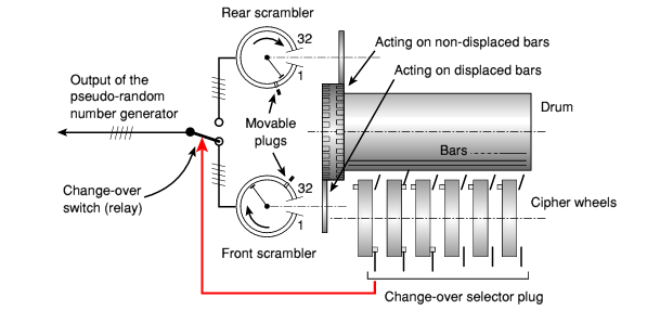
Operation is further explained in this simplified diagram:
| |
|
Simplified diagram of the 'Converter' and scramblers
|
To make matters even more complicated, the operation of the rear
cylinder is inverted.
In other words: the contact arm of the front cylinder is moved by a
displaced bar in the drum, whilst the contact arm of the rear cylinder
is activated by an undisplaced bar.
The total number of steps (of both cylinders added together) is always
12.
As a result, the machine produces two key-series and we have to choose
between them. This is done by means of a change-over switch that is
activated by one of the six key wheels.
The operating point of the keywheel that is used, is displaced about 90°
from the operating point of the bar-shifting lever.
The absense of a pin selects the front cylinders, whilst the presence
of a pin selects the rear (inverted) cylinder.
A movable plug at the front of the machine is used for selection of
the wheel that is used for switching between the two cylinders.
It can be inserted (and fixed) in only one of the six possible
positions at any given time. The position of the change-over plug
was part of the key-settings.
|
|
|
|
|
|
|
When using the internal PRNG (i.e. the mechanical Converter machine),
there are two sets of key elements that should remain secret. These are the
internal and external key settings.
Internal keys
- The positions of the 2 x 32 five-contact plugs on the two contact cylinders.
- The positions of the lugs on the 24 bars of the drum.
- The positions of the pins in the 6 key wheels.
External keys
- The starting positions of the 6 key wheels.
- The starting position of the drum (even or odd half turn).
- The starting position of the selector scanning arms of the contact cylinders.
- The position of the change-over contact plug.
|
Below is a quick overview of the various controls on the front panel of
the TC-52. The two main power switches are on the right. The rightmost one
is the mains power switch and the one next to it allows the motor to be
switched off when pausing transmission.
At the centre are three lever-operated switches, similar to the switches
of an old-fashioned telephone. These switches are used to control the
mode of operation of the TC-52. The counter is used for counting the
number of transmitted characters.
The big knob at the far left can be used to advance the drum by half a
cycle (when in receive mode), so that the correct starting position
(even or odd half of the drum) can be selected.
More information about the operation of the TC-52 can be found in the
original instruction manual that was supplied with the machine. As this
manual was stencilled with rather poor quality ink on thin paper, it is
nearly impossible to make high-quality scans.
We have therefore made a complete transcript of the manual, which
is available for download below.
|
The TC-52 was supplied in a sturdy black transit case, or sometimes in a
so-called letherette.
The black sturdy case allows the machine to be transported
safely, and prevents it from getting damaged.
The machine is seated on a horizontal base plate and is held in place
by a rubber frame. The frame itself rests on a rubber shock-mount.
|
After opening the case, the machine is easily
accessible, as can be seen in the picture on the right.
For operation, the machine must be taken out of the case,
whilst the base plate remains attached to the bottom of the machine.
The base plate is attached to the case by means of a short black ribbon,
so that it can not be separated from the case. The machine is either
operated whilst standing on the base plate, or is released from the
rubber frame prior to being installed.
The ribbon is visible in images #6
and #7 below.
|
|
|
The cables and spare parts for the TC-52 are stored in the bottom of
the transit case, below the machine. The cables are wound on a set of
spools and are held in place by a couple of straps.
The spare parts are stored inside a long rectangular box, as can be
seen in images #7
and #8 below.
This includes a spare XOR unit and some carbon brushes.
|
The TC-52 connects to the outside world by means of only two cables:
a standard power cable, that connects the machine to the mains, and a
very special data cable, that is used for connection to a teleprinter and the
transmission line (radio or telex).
|
Connection to the mains is rather straight forward.
Depending on the version, the TC-52 can be connected to a range of
different mains voltages. When connecting a unit, always check the
position of the power selector first. it is located at the rear of the machine,
close to the motor (check the rightmost images below).
The supplied (rubber)
cable has a 'standard' Hagelin mains plug on one end
(see image #3 below).
This plug should be entered into the mains socket at the rear of the TC-52.
The other end should have a local mains plug.
|
|
|
Connection to a teleprinter and the teletype exchange (telex) is slightly
more complicated. They are both connected via a single cable that should be
supplied with the machine. The cable has a 5-way Tuchel connector at one
end, that plugs into the interface socket at the rear of the TC-52.
Tuchel connectors are extremely rare these days so, if you have one,
hang on to it!
|
The data cable with the Tuchel connector has 5 coloured wires:
|
|
Colour
|
Polarity
|
Direction
|
Description
|
|
Red
|
+
|
IN
|
Teleprinter
|
|
Grey
|
-
|
IN
|
Teleprinter
|
|
White
|
+
|
OUT
|
Transmission line (telex)
|
|
Black
|
-
|
OUT
|
Transmission line (telex)
|
|
Yellow
|
-
|
DC
|
Ground
|
|

| |
|
Wiring of the Tuchel connector when looking into the socket of the TC-52
|
The TC-52 is intended for connection to teleprinter equipment which has the magnet and
the sending contact connected in series, and 40 mA single current operation. Power for this
is supplied by the TC-52.
The transmission line should also be 40 mA single current operation, where power is supplied
by the external party (i.e. the transmission line).
|
|
|
Other Hagelin on-line Telecrypto machines
|
|
|
|
- T-52
- T-55
- TC-55
- TL-520
- TMX-53
- CBX-53
|
|
|
|
Any links shown in red are currently unavailable.
If you like this website, why not make a donation?
© Copyright 2009-2013, Paul Reuvers & Marc Simons. Last changed: Monday, 08 July 2013 - 17:26 CET
|
 |

|
|


")
.")


")


