|
|
|
|
|

|
Portable Radio with Digital Encryption
The Philips PFX-PM was a portable half-duplex radio with digital
encryption. It was based on a PFX radio, built by Philips
Radio Communication Systems (RCS, formerly: Pye) in Cambridge (UK).
In 1990, Philips Usfa developed the
UP 2093 half-duplex crypto module
that fitted in the lower part of the extended version of the PFX radio.
Differt versions of the crypto-module were made.
|
The image on the right shows the extended version of the PFX-PM, with detached
battery. It is longer than the standard version. The small instruction booklet (TP1962) is also shown here.
Two basic versions of this radio exist: one for the 2-meter band
(150 MHz) and one for the 70-cm band (400 MHz). The 2-meter
version was available in various frequency ranges.
The radio shown here is of the type PFXPM LVA, which means it's a
low-power version (L) with 25 kHz channel spacing (V) and a frequency
range of 148-162 MHz or 160-174 MHz (A).
|
|
|
The exact details of this PFX radio can be found on Jan Buiting's
website about his Philips Mobile and Portable radio Collection.
Please note that the frequency range is either 148-162 MHz (A1) or
160-174 MHz (A2) but not both. One can only tell the difference by opening
the unit.
The reason for using 25 kHz channel spacing rather than 12.5 kHz,
is that digital delta modulation is used for the transmission of voice
data. This requires a bandwidth of at least 16 kHz in order to obtain
a good voice quality.
|
The entire crypto unit consists of three stacked PCBs plus a sealed
Crypto Module developed and manufactured by Philips Usfa.
By fitting components on both sides of each PCB, they managed to fit
the complete assembly in the CTCSS compartment of the extended
version of the PFX.
|
The three stacked PCBs contain the AD converter, Delta Modulator, the
DA converter, additional audio circuits and some glue logic.
The actual encryption and decryption of the data takes place in the sealed
UP 2093 crypto module shown in the image on the right.
The crypto module itself consists of a PCB with components on both sides
(see below).
The image on the right shows the complete stack of three PCBs with the
crypto-module on top. At the front is the 3V lithium battery.
|
|
|
The top part of the crypto module cannot be opened as it is sealed in some
kind of very tough foam than can't be removed without damaging the components.
The rather unique photographs below, show the interior of the crypto-module.
this prototype was used during the development.
|
The crypto-module is in fact a PCB with four chips at the
top surface.
At the top right is the custom-made OQ4434 crypto-chip (ASIC) with its typical
golden top cover. The image on the right also shows a couple of bare OA4434
chips, one of which is missing its golden roof.
At the top left is a one-time programmable Intel 87C51 microcontroller that contains the control firmware.
At the front are two Programmable Array Logic ICs (PALs).
The other side of the PCB (bottom)
contains the buffers and the glue logic to interface to the rest of the radio.
|
|
|
|
With every crypto system, the creation and distribution of the key(s)
requires special attention and security measures. The PFX-PM is no exception
to this rule. Philips RCS created a special programming kit for the
creation and distribution of up to four different keys.
|
The kit consisted of a software package that converted a standard PC (DOS)
into a Master Key Programmer (MPK). With the software, the person responsible
for the key generation could manually enter 4 different keys in hexadecimal format.
The software could also generate random keys.
Once generated, the Slave Key Programmer (SKP) would be used to transfer the
key material to the various PFX-PM radios (keyfiller).
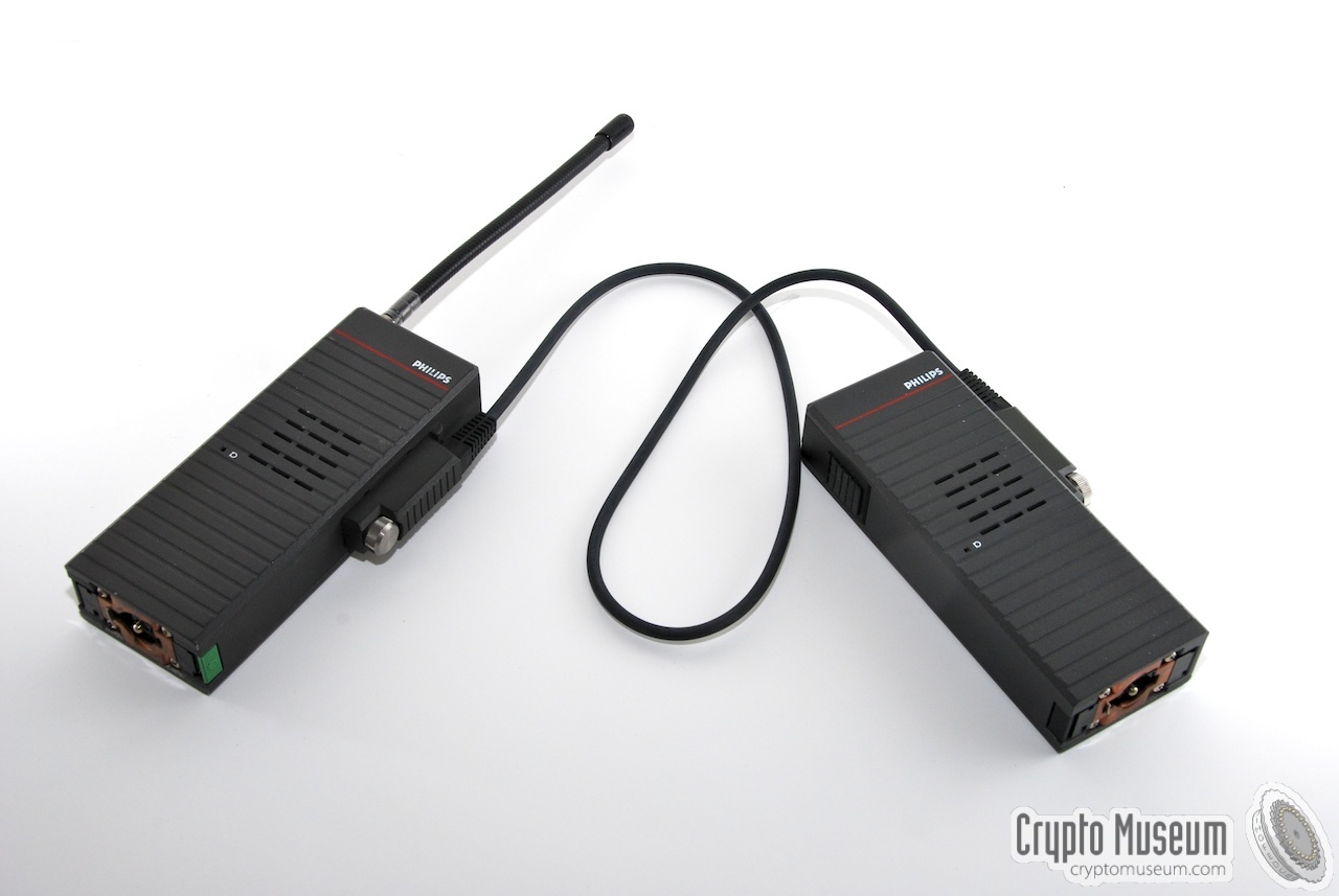
The image on the right shows an SKP connected to a PFX-PM radio with a special
transfer cable.
|
|
|
The SKP (right) is housed in the case of a PFX radio.
Please note that both the radio and the SKP should be powered by their own
batteries (not shown here).
The special transfer cable has identical connectors at both ends,
allowing it to connect to the accessory socket of the radio.
The SKP could also be used to transfer the keys to further SKPs.
The SKP has two buttons. One on top of the unit (test) and one on the side for
starting the transfer (the former PTT button). The speaker of
the SKP is used for communication with the user. A single beep indicates an error,
whilst a double beep is sounded after a successful transfer of key material.
A low-battery condition is indicated by three short clicks on the speaker of
the SKP.
Changing the battery should take less then one minute in order not to lose
the key material stored in the SKP's memory.
The SKP cannot be turned off and will always
consume a little bit of power in order to retain the keys.
Please note that the PFX-PM allows 8 crypto keys to be programmed,
whilst the SKP software only allows 4 different keys to be set.
This is because a longer 5th key is permanently set by the software
(hard-coded), allowing secure communication even when the keys are lost.
|
|
|
|
|
|
|
- Philips RCS, PFX-PM Portable Radio with Digital Encryption, Operating Instructions
TP1962, 1 November 1989
- Philips RCS, Master Key Generator and Programmer (MKP) for PFX-PM, User Manual
TP875, 1990
- Philips RCS, Slave Key Programmer (SKP), User Guide
TP1992 issue 1, 1990
- Philips RCS, Philips digital secure speech system
Brochure with all Philips crypto radio products.
|
|
|
|
Any links shown in red are currently unavailable.
If you like this website, why not make a donation?
© Copyright 2009-2013, Paul Reuvers & Marc Simons. Last changed: Friday, 19 August 2011 - 10:36 CET
|
 |

|
|


. At the right the interior of the module. At the front the bare crypto-chips.")


")

 for the Master Key Programmer (MKP)")