|
|
|
|
|

|
Hand-held text encryptor
The TST-3010 was a high-end military-grade hand-held message encryption system
developed in the early 1980s by Tele Security Timmann (TST)
in Tutzing (Germany) for use by Governmental and Military users.
It was available with LCD or LED display and was suitable for Latin
and Arabic.
|
The unit is housed inside a ruggedized metal case that measures only
29 x 10.5 x 3.5 cm. It can be powered by batteries as well as from the mains
and allows messages to be sent via standard analogue telephone lines,
using an acoustic coupler,
and over narrow-band radio channels.
The TST-3010 was available in several versions and in a variety of
languages. For use by the Army it was normally supplied inside a green
ruggedized case, together with a printer and a power supply unit,
as shown below. It was also available as a self-contained
stand-alone unit.
|
|
|
As the TST-3010 has its own built-in voltage regulator, it
can be powered by any DC source between 10.5V and 32V, making it suitable
for simply battery operation, as well as for use in cars (12V) and
(military) trucks (24V). The unit was available with an LCD screen, but
could optionally also be supplied with an LED display. Power consumption
was approx. 1W with an LCD screen and 4W when a LED display was used.
The external TST-3040 Power Supply Unit supplies 18V DC.
The version shown here however, was probably intended for use by
Army Officers whilst travelling. It is housed inside a
lightweight flight case-style green briefcase,
with just the TST-3010 and the
TST-3070 Acoustic Coupler. The TST-3010 has been modified to take
5 AA-size penlight batteries. Furthermore, it has (civil) DIN
connectors at the side, rather than the more usual military ones.
The TST-3010 was the military alternative to the
TST-3550 and was in production for many years.
|
|
|
|
|
|
|
- TST-3010 Terminal
- TST-3030 Printer
- TST-3040 PSU
- TST-3050 Battery Unit
- TST-3060 Paper Tape Reader Interface
- TST-3070 Acoustic Coupler
- TST-3000-912 Shock resistand mounting plate
|
The TST-3010 can be used stand-alone, or as part of a complete system.
It can also be used in combination with a variety of radio transceivers,
in which case the device can be powered by the radio. When used stand-alone,
it is usually powered by a battery unit or an external PSU.
|
The battery unit or the mains PSU had the same size as the TST-3010
itself, and could easily be placed underneath it.
A rather common configuration is shown in the image on the right.
The TST-3010 is used here in combination with the TST-3030 thermal
printer which is connected to the NF10 socket on the left.
This configuration was often supplied in a light-weight green metal
briefcase as well.
|
|
|
|
Although the TST-3010 was intended for use as a secure military message
device, it was also used for civil and semi-civil purposes, such communication
between embassies, diplomats and officers on the move. The civil version
was also housed in a light-weight green briefcase.
|
The image on the right shows a typical TST-3010 configuration in such a
green briefcase, together with the TST-3070 acoustic coupler.
As TST products were particularly popular in the Arab countries,
it could optionally be supplied with a keyboard in the Arabic language, such as
the one shown in the image. The firmware in such machines was modified
so that the device would select Arabic by default at power on.
The version is the image is rather special, as it has a built in battery
compartment at the back.
|
|
|
For this, the case has been modified to hold five AA-size (penlight)
rechargeable NiCd batteries. A small mains adapter is supplied (in the
top left), in order to charge the batteries when travelling.
Also special on this version is that the military NF-07 and NF10 sockets
at the left side have been replaced by 7-pin and 8-pin DIN sockets
which were commonly available from civil stores.
|
The TST-3010 was also available in a ruggedized military case,
together with a battery unit and a half-page (40 columns)
thermal printer. The system was known as TST-3000.
The complete TST-3000 set is shown in the image on the right [1].
A latin version of the TST-3010 is shown at the front. Below
the TST-3010 is the TST-3050 battery unit. The rear half of the
case is taken by the rebatched Hitachi TST-3030 thermal printer.
Below the printer is the (optional) TST-3040 AC Power Adapter.
The TST-3010 featured on this page can be seen a simplified
version of the TST-3000 system shown on the right. It is packed
in a smaller (lightweight) briefcase and has been modified to
hold the batteries inside the main unit. Furthermore, it has
DIN sockets on the side rather than the typical military connectors.
|
|
|
|
|
|
TST-3040 Power Supply Unit
|
 |
|
|
The image on the right shows the TST-3040 power supply unit that is
house in a metal enclosure that is similar in size to that of the TST-3010
itself. Both units could be
stacked.
The TST-3040 delivers 18V DC to the TST-3010, which is regulated down to 5V DC
inside the TST-3010.
The TST-3050 Battery Unit was housed in a similar case,
but the TST-3010 shown here was modified with its own internal
battery compartment
at the bottom.
|
|
|
|
|
|
TST-3070 Acoustic Coupler
|
|
|
|
For business men and embassy personnel on the move, the TST-3010 was
often used together with the TST-3070 acoustic coupler [6].
In the configuration shown here, it was built inside the flight case,
behind the main TST-3010 unit. It can also be used as a stand-alone unit.
|
The image on the right shows how the handset of a standard telephone
set was placed in the coupler.
Foldable rubber lens caps,
of a standard photo camera, were used to
keep the handset in place and shield off ambient noise.
The same acoustic coupler was used with the
TST-3550 cipher machine.
More images below.
Inside the acoustic coupler
is a complete 300 baud AFSK modem,
which is connected to the TST-3010 via TTL-level RX and TX signals
(see below). Power (+5V) for the circuitry inside the TST-3070
is supplied by the TST-3010 itself.
|
|
|
|
The TST-3010 was available with two different character sets.
The standard version used the Latin character set which is used by
most West European and American countries. As the TST-3010 was very popular
in countries such as Saudi Arabia, it was also available in Arabic.
|
The image on the right shows the Arabic version of the TST-3010,
which is currently asking for a command to be entered via the keyboard.
It had an Arabic keyboard layout and started up in the Arabic language,
writing from right to left.
Whenever necessary, it is possible to switch over to Latin with just
two key strokes: 0 (OPTION) followed by 8 (LANGUAGE).
The system then switches to the Latin character set, writing from left to
right, showing its commands in English.
The unit could be converted permanently
by swapping the matal keyboard overlay.
|
|
|
In our case, the TST-3010 came with an Arabic keyboard layout, starting
up in Arabic. Luckily, the
Latin keyboard overlay was also supplied in
a corner of the briefcase. After the keyboard has been removed from
the main unit (see below), the metal keyboard overlay can easily be replaced.
|
The TST-3010 is housed in a sturdy low-profile extruded aluminium enclosure,
similar to the ones that TST used for other products, such as the TST-7595
Voice Scrambler, and a number of accessories for the TST-3010,
like the TST-3040 Mains PSU and the TST-3050 Battery Unit.
|
The interior of the unit case be accessed from the left,
by loosening four hex screws
at the top and bottom at the left,
after which the connector panel
can be removed. Inside the case are two PCBs
that are slotted into rigs at the sides.
The connector panel is connected to both PCBs via two
ribbon cables that can easily be removed.
Before the PCBs can be removed, the keyboard needs to be removed
by releasing the four screws at its corners. The keyboard is connected
to the main PCB via a header at the left and can be removed by pulling
it away from the case.
|
|
|
Once the keyboard has been removed and the connector panel is disconnected,
the two PCBs can be pulled out of the case. The upper PCB is the actual
computer board, which is built around a
National Semiconductor NSC800 processor,
the military variant of the Zilog Z-80 processor. The main board is marked
TBU 994/1 and the EPROM (to the right of the processor) has 'TBU' on it.
|
The main board
extends to the full width of the case and has two daughter
boards: an Hitachi 1 x 40 characters LCD screen,
and a matching character generator.
The character generator is soldered in place at the
bottom right, whilst the LCD is
mounted over the top half
of the PCB.
It can be removed by releasing the four screws in the corners and taking it
out of its connector at the right. The actual computer takes only the
left half of the main PCB.
The image on the right shows the main PCB after
the display has been removed. It connects to the character generator.
|
|
|
In an earlier version of the TST-3010,
an EPSON 1 x 40 character display with the same size was used.
It came with its own character generator which was mounted over
the bottom half of the main board. The display itself had two connectors,
one at the left and one at the right, through which it was attached to the
main PCB. This required a different layout of the main PCB.
|
Mounted below the main PCB is the crypto card,
which is about 2/3rd
of the length of the main PCB, leaving enough room an
internal battery compartment.
This battery compartment was not available in the earlier
version of the TST-3010.
The crypto board is marked SYS 994, and is built around a
SHARP LH5080L,
a 2.5 MHz variant of the Zilog Z-80. It is driven by a 2.4576 MHz crystal
that is mounted on the same board. This frequency was probably choosen
carefully, so that the correct baud rates and AFSK tones for the acoustic
coupler are generated accurately.
|
|
|
The battery compartment is identical to that of the TST-2007
(a hand-held secure spread-spectrum radio) and probably some other
products as well.
It is permanently fitted (i.e. glued) inside the case.
It connects to the crypto board by means of a red/black cable.
This way, the static memory on the board is retained when the
unit is switched off. The key memory is further protected by a 3V
Lithium battery
that is mounted in the lower right corner of the crypto board.
From the crypto board, the power line runs
via the ON/OFF switch at the side
to the main PCB.
|
- 1 Input
- 2 Read (edit)
- 3 Print
- 4 Encipher
- 5 Send
- 6 Delete
- 7 Decipher Tape
- 8 Decipher Message
- 9 Keys
- 0 Option (see below)
- ( End
- ) Format
|
|
|
- 1 Change password
- 2 Change modem speed
- 3 Receive protocol on/off
- 4 Encipher numbers
- 5 Send message to different address
- 6 Delete all messages
- 7 Self test
- 8 Language
- 9 not used
- 0 Manual reply
- ( Error reply
- ) Station request
|
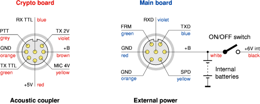
At the left side are two sockets for the connection of power supply units,
an acoustic coupler, a radio and other peripherals. There are two known
standards: with two DIN sockets and with two German NF10 military sockets.
At present, the pinout of these sockets is largely unknown.
The above drawing shows the colours of the internal wiring. The socket
with the red labels is connected to the crypto board (i.e. the lower board),
whilst the socket with the blue labels connects to the main board. Note
that power is fed into the rightmost socket, but is led to the lower board.
If you have more information about these connections, please
contact us.
|
|
Name
|
TX-3010
|
TX-3070
|
Description
|
|
|
|
+B
|
Brown
|
Brown
|
Raw DC power input
|
|
+5V
|
Red
|
Red
|
Switched power
|
|
GND
|
Orange
|
Pink
|
Ground (0V)
|
|
MIC 4V
|
Yellow
|
Yellow
|
Microphone signal 4V pp
|
|
TX TTX
|
Green
|
Green
|
Transmit signal (5V TTL level)
|
|
RX TTL
|
Blue
|
Blue
|
Receive signal (5V TTL level)
|
|
TX 2V
|
Violet
|
-
|
Transmit signal (2V pp)
|
|
PTT
|
Grey
|
-
|
Push-To-Talk signal (PTT)
|
|
|
Name
|
TX-3010
|
TX-3040
|
Description
|
|
|
|
+B
|
White
|
Red
|
Raw DC power input
|
|
GND
|
Red
|
Black
|
Ground (0V)
|
|
SPD
|
Yellow
|
-
|
Speed select
|
|
GND
|
Orange
|
-
|
Signal Ground (0V)
|
|
FRM
|
Green
|
-
|
Format
|
|
RXD
|
Violet
|
-
|
Receive data
|
|
TXD
|
Blue
|
-
|
Transmit data
|
|
|
|
|
Any links shown in red are currently unavailable.
If you like this website, why not make a donation?
© Copyright 2009-2013, Paul Reuvers & Marc Simons. Last changed: Sunday, 15 September 2013 - 17:44 CET
|
 |

|
|

")


![Military version of the TST-3000 series [1]](img/tst3000sys.jpg "Military version of the TST-3000 series [1]")


")


 with Hitachi display")

")


")
")
![Interior of the TST-3010 [1]](img/tst3010_interior.jpg "Interior of the TST-3010 [1]")