The STU-II was the second generation
Secure Telephone Unit (STU)
introduced by the NSA in the 1980s.
It replaced older systems, like the extremely bulky KY-3,
and was the
successor to the STU-I.
The STU-II is also known as the KY-71 or TSEC/KY-71.
It uses an LPC/APC vocoder and the GCHQ/NSA-developed
SAVILLE encryption algorithm.
It came as a two-piece system.
In the 1990s, STU-II was replaced by the much smaller
STU-III
and (for NATO) by the STU-II/B.
The STU-II was built by ITT, using Northern Telecom as a sub-contractor.
The unit consisted of a large metal cabinet that contained the electronics
(the actual KY-71) and a telephone-style desktop unit, known as the HYX-71,
that acted as the terminal (user interface).
The image on the right shows the HYX-71 desktop unit, that was connected to
the KY-71 cabinet by means of a 9-way cable.
It's a fairly large telephone set, with a standard handset,
a normal numerical keypad, some
indicator LEDs and three extra buttons at the bottom.
Once a call had been established in CLEAR mode, the user had to press the SEC-button
to 'go secure'.
As the STU-II uses the same LPC-10 vocoder as the later
STU-III, there is always a 10 to 15 second delay
before secure mode is activated. During this stage, the keys are exchanged.
In addition, it was also possible for the calling party to initiate a call
directly in encrypted mode.
Voice data was transferred at 2400 baud, resulting in a very synthetic sound.
Although speech was relatively clear, it was impossible to recognize the speaker
at the other end. Certain versions of the STU-II were able to use 9600 baud,
but given the rather poor quality of telephone lines, 2400 baud was used in
most cases. When in half-duplex secure mode (simplex), the user had to press the
so-called Push-To-Talk switch (PTT), inside the grip of the receiver, when speaking.
Key material was handled by a so-called Key Distribution Center (KDC), which
was NSA operated. Keys were transferred to the STU-II by means of a
KOI-18
(paper-tape) or KYK-13 (electronic)
key transfer device.
Approximately 10,000 STU-II units were built [1].
Over the years, a number of STU-II compatible devices were introduced,
including the Dutch Spendex 40.
In the US, the STU-II was replaced in the
1990s by the much smaller, far cheaper and more capable
STU-III.
For use by the Army and for NATO, it was replaced by a special version
of the STU-III,
known as STU-II/B.
Complete setup
Although the STU-II was much smaller than its predecessor, the
STU-I,
it was still too large to be placed on a desktop. For this reason, the unit
was housed in a separate case (the KY-71), whilst special telephone sets were
used to control it (the HYX-71). The drawing below shows the basic setup of
the STU-II. The reason for the strange sloped design of the KY-71 case is
unknown.
The sloped front panel of the KY-71 holds a control panel that is used for
selecting the mode of operation and for loading the key variables. It also
has a 2-digit 7-segment display that shows the current state of the device
and a slot (at the bottom left) for the Crypto Ignition Key (CIK).
The right half of the control panel holds the 9-position MODE selector
and the INITIATE button. The latter is used to initiate a KEY-loading
operation or for selecting the appropriate key variable. During normal
operation, the MODE-selector is either set to KDC or NET. In KCD mode,
the unit relies on the presence of an external so-called
Key Distribution Center that is called for activation of the keys.
The KDC no longer exists today.
At the far right are two slide-switches. The upper one
is used to set the data transfer speed of the terminal at 2400 baud (24)
or 9600 baud (96). The lower switch is used to select between
Half-duplex (HDX) and Full-duplex (FDX).
Multiple extensions
By using an (optional) expansion unit, the so-called J-BOX or Junction Box,
it was possible to connect up to five additional HYX-71 telephone sets to the
KY-71. The J-BOX consisted of a rectangular metal case with 7 sub-D
sockets (2 x 25-way and 5 x 15-way female sockets). It had no controls
or indicators and was usually built inside a 19" rack, together with the KY-71.
The image above shows the layout of the connector panel of the KY-71 J-BOX.
The 25-way socket at the left connects the J-BOX to the KY-71 terminal.
The next five sockets are used for connecting the additional
HYX-71 telephone sets. A complete multi-user setup looks like this:
The KY-71 can handle only one call at a time. Any incoming call is routed
to the handset that is picked up first. When a handset is dialling out,
the other handsets can not be used to place a call. In a multi-user setup,
the KY-71 can be used as a mini-PABX and calls can be placed between
the extensions by dialling their single-digit number. They can also be used
for conference calls.
Crypto Ignition Key
The KY-71 introduces the concept of a so-called Crypto Ignition Key (CIK).
The CIK-71 is a rectangular module that should be inserted into a special slot
to the left of the control panel. It contains a small non-volatile memory
unit that is used to store the Key Encryption Key (KEK).
The image above shows an educated guess of what the STU-II CIK looked like.
It had a metal enclosure with a connector at the bottom. The metal tag at
the top contains the product ID (CIK-71) and the serial number. When loading
key variables into the KY-71, the keys are encrypted with a so-called
Key Encryption Key (KEK) that is randomly generated by the terminal. The
KEK is then stored inside the CIK. This way, the KY-71 and the CIK are paired.
When the CIK is removed, the key variables
inside the KY-71 become meaningless. Likewise, a bare CIK is useless on
any other KY-71 terminal and does not reveal any information about the
actual keys.
Key loading
The KY-71 has a standard (5-pin or 6-pin) U-229 socket
for the connecting
of a key distribution device or key filler,
such as the KOI-18
or the KYK-13.
Each KY-71 can hold two key variables: a NET variable (VN),
for keys that are shared between multiple parties,
and a UNIQUE variable (VU).
Key variables for the STU-II were supplied on 8-level paper
tape and read into the device with a KOI-18
or a similar device.
The KOI-18 was connected to the FILL socket of the KY-71 by means of a short
cable and the MODE selector on the KY-71 was set to LOAD.
After pressing the INITIATE button,
the tape was slowly pulled through the key filler at a constant speed.
It was also possible to use a KYK-13 key filler.
In that case, the KOI-18 was used to load the key variables into the
KYK-13 and the KYK-13 was then used to load the keys into the KY-71.
The advantage of using a KYK-13
is that it can hold up to 6 different
keys in its internal memory. The image above shows how the KYK was used
to load keys into a KY-71 terminal [17]. The KYK-13 is mounted directly
to the FILL socket of the KY-71. After selecting the required key variable
compartment on the KYK-13, the INITIATE button of the KY-71 is pressed.
During key loading, the ALARM light should briefly flash.
Once the key is loaded, the display should show '01'.
Zeroizing
In case of an imergency, the crypto variables that are stored
inside the KY-71 should be purged immediately by executing the
ZEROIZE procedure. This should also be done when the loaded keys
are no longer needed. Zeroizing is a 2-step operation.
Press the ZEROIZE knob and rotate it to the
ZEROIZE position. Then turn the knob back to NORMAL
in order to resume normal operation.
History
The history of the STU-II starts with the development of the earlier and
bigger STU-I device in the late 1960s and early 1970s,
after the NSA had recognised telephone communication as one of
the major security threats.
Initially it was tried to solve this issue by setting up
AUTOSEVOCOM, a secure version of the existing Defence Communication
System (DCS), called AUTOVON.
This system appeared to be too expensive
and too cumbersome and was abandoned in the late 1960s, after some
1850 terminals had been installed [2].
Problems with existing systems had shown that speech quality was too bad
on narrowband systems, and that it was difficult to distribute
cryptographic key material to the users. As a result, many users were still
using standard (plaintext) telephones.
In the late 1960s, the NSA defined the design goals for a digital Secure
Telephone Unit (STU) that would solve the existing problems.
The problem of voice quality was solved by using a revolutionary technique
called Linear Predictive Coding (LPC), which greatly improved voice quality
in narrowband systems. The key distribution problem was solved by introducing
the concept of the Key Distribution Center (KDC).
In the light of the Vietnam War, GCHQ
and the NSA had developed a highly secure
light-weight high-quality encryption algorithm, known as
SAVILLE,
for use in COMSEC devices such as VINSON KY-57
and KY-58.
The same SAVILLE encryption algorithm was used in STU family [4].
The first generation of the new system was called STU-I
and was technically successful in that it allowed secure voice communication
in full-duplex over standard (analogue) telephone lines, with a relatively
good speech quality.
Other design goals, such as the size of the unit and the price tag,
had failed. So immediately after the introduction of the
STU-I,
the NSA started development of the 2nd generation, known as STU-II,
which should be much smaller and more affordable.
Development of the STU-II took from 1977 to 1980, and the units were in
production from 1982 to 1986 [3]. By 1986, some 10,000 units had
been delivered to a range of (approved) users world-wide. At US$ 13,000
per unit, the STU-II was much cheaper than its predecessor the STU-I
(at US$ 35,000 per unit), but still way above the initial target price of US$ 5000.
Although the STU-II was about half the size of the STU-I, it still wouldn't
fit on a desktop and was commonly installed in large cabinet similar to the
one used with the STU-I. The image on the right shows a photograph [9] of an
STU-II unit that is on display at the NCM [10].
It is currently unknown whether any complete STU-II units (apart from
the handset) have survived.
The STU-II was in operation during the Reagan Administration (1981-1989) [12]
and was used on several occasions (see below).
Being keen on secure communications, President Reagan strongly supported
the wide-spread use the STU-II, and in 1982 Deputy Secretary of Defense Frank
Carlucci, decided to buy 5,000 STU-II sets and allocated US$ 120 million
for the program [13].
In 1982, at an evaluation meeting at the DoD/DARPA [7], Joel Feldman of
MIT Lincoln Laboratory demonstrated a single board LPC coder that was
built around three NEC µPD7720 first-generation DSP chips.
Around the same time, Philips Usfa
in the Netherlands, introduced the
STU-II compatible Spendex 40 unit,
that had a
nearly identical implementation
of the LPC vocoder.
This proved that it was possible to implement the entire STU-II system
as a desktop unit, and convinced the director of the NSA to initiate
the development of the STU-III[3].
Instruction videos
From an anonymous donor we receiver the following two instruction
videos about the use of the STU-II [16][17]. The videos were issued
in the late 1970s and were intended For Official Use Only.
We have tried to identify the original copyright holder of these
videos, but since they are not mentioned in the recording, nor on
the original video tape, we have not been able to seek approval.
As the material is now over 30 years old and the equipment is no
longer in use, we have decided to publish them anyway.
Anyone claiming copyright is requested to
contact us directly.
your STU-II'
[16] and contains
a brief introduction in the various components of the STU-II
and its use. It shows how to enter the Crypto Ignition Key (CIK),
how to place a call in initial clear or initial secure
mode, and how to connect multiple telephone sets.
above video,
titled 'STU-II rekeying'[17] shows how keys were entered
into the KY-71 by means of KOI-18
or KYK-13 key fill device.
It also shows how the keys, distributed on punched paper tape,
could be transferred from a KOI-18 to a KYK-13.
President Ronald Reagan
Whenever an American president is travelling or is on holidays, he
needs to be able to speak with his advisors and staff at the
White House and the Pentagon within seconds whenever emergency strikes.
A the time of the STU-II, it would be installed in a room in the
vicinity of the president.
Invasion of Grenada
In 1983, the Caribbean Island of Grenada with its 91,000 population,
lost its revolutionary government to a bloody military coup.
Grenada is a former UK colony that became independent in 1974.
As it is located south of the United States (and east of Cuba),
the Organization of American States (OAS) asked the US to intervene.
The US started planning Operation Urgent Fury on 22 October 1983
and started the invasion of Grenada just a few days later on 25 October
1983 [14].
Around the time of the coup, US President Ronald Reagan was staying
at the Augusta National Golf Course in
Georgia (US). As the invasion would take place less than three days
later, it was important to have secure conversations with the Pentagon.
The image above shows former US President Ronals Reagon at the
Eisenhower Cabin at the Augusta National Golf Course where, late
in the evening of 22 October 1983, he uses a STU-II.
Please note that the telephone-style unit on the table is just the
STU-II terminal; the actual STU-II is probably located in the next
room [15].
The image above is taken around the same time as the previous one.
It shows National Security Advisor Bud McFairlane (left), Secretary
of State George Schultz (center) and President Ronald Reagan (right)
in the Eisenhower Cabin at the Augusta National Golf Course in
Georgia (US) on the evening of 22 October 1983. The STU-II is still
visible on the table at the right of the image [13].
Spendex 40
Shortly after the development of the STU-II had been completed (1980),
Dutch Defense contractor Philips Usfa started
development of a STU-II compatible crypto phone that would fit on a desktop
whilst meeting the (TEMPEST) requirements of the Department of Defence (DoD)
and NATO.
The new unit was called Spendex 40
and was introduced around 1983, shortly after the STU-II had gone into
production. Although relatively large and heavy, the Spendex 40
was much smaller than the STU-II and was a truely portable device.
It is shown in the image on the right.
Spendex 40 was available in a 2-wire and 4-wire version,
and introduced the concept of the CIK (Crypto Ignition Key),
a large blob connected at the front, that was used to protect the crypto
keys stored inside the device. Keys were loaded by means of a standard
fill device (e.g. KYK-13).
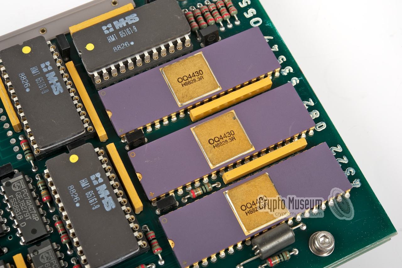
By special arrangement with the NSA, Philips was one of the
first companies to be allowed to implement the highly secret
SAVILLE algorithm
in their own custom-designed
crypto chip, the OQ4430. This enabled
Philips to sell the Spendex 40 to the Dutch Government and to NATO.
Philips had managed to implement a much smaller version of the LPC-10 vocoder,
by building it around three NEC µPD7720 first-generation DSP chips,
nearly identical to the LPC implementation of MIT Lincoln Laboratory
that was demonstrated to the director of the NSA on 3 June 1982 [7].
According to eye-witnesses at Philips Usfa in the early 1980s,
visiting NSA inspectors were suprised by the higher speech quality and the smaller size compared to the STU-II [8].
In the light of a bi-lateral agreement between the USA and NATO,
some European countries were allowed to develop their own STU-II compatible
devices.
Following the Philips Spendex 40
in the early 1980s, Siemens
developed the Elcrovox 1/4 in the late 1980s.
The initial version implemented SAVILLE in firmware, but was turned
down by the NSA. Siemens then developed a dedicated SAVILLE encryption chip.
Shortly after development of the STU-II was finished (1980), Joel Feldman
demonstrated a single-board implementation of the LPC vocoder at a DoD/DARPA
meeting on 3 June 1982 [7]. The new vocoder was based around three NEC
µPD7720 first-generation DSP chips and was developed at the Lincoln Laboratory
at MIT. It proved that a much smaller implementation of the device was possible
and that DSP-technology at the same time offered improved speech quality.
Around the same time, Philips Usfa engineers successfully implemented a nearly
identical LPC vocoder in the new
Spendex 40 (see above)
and it too had improved sound quality [8].
These experiences proved that is was possible to create a single-unit STU
device that would fit on a desktop. In 1984 development was started
of the next generation STU-III devices that would be
even smaller.
Production of the STU-III started in 1987 and lasted well into the 2000s.
Most units were built by Motorola
(e.g. SECTEL).
In the early 1990s, the NSA introduced the STU-II/B.
It was built by Motorola and was intended to
replace all STU-II compatible devices, including the STU-II itself and the
Philips Spendex 40.
The design was based on the new STU-III hardware,
but for historical reasons the designator STU-II/B was used for the Army.
This was probably done to allow a smooth transition from the original STU-II.
The most significant difference with the STU-III,
was the presence of a standard U-229 socket
at the rear of the device, allowing a key filler,
such as the KYK-13, to be connected.
Compared to a standard DTMF telephone set,
the STU-II terminal has
an extra row of keys to the right of the usual keys.
These keys were provided for compatibility with the AUTOVON (and later: ISVN)
non-secure telephone network used world-wide by the Department
of Defence (DoD) [11].
AUTOVON (Automatic Voice Network) was a military phone system that was
built in the US in 1963. It was designed to survive nuclear attacks
and allowed non-secure voice calls with precedence (piority override,
see below).
Using STU-II over AUTOVON allowed secure voice calls over a non-secure
network. Later secure terminals, such as the STU-II/B
and the Spendex-40
featured the same AUTOVON compatibility.
In the late 1960s, the DoD started the roll-out of a secure version
of AUTOVON, called AUTOSEVOCOM, but this project was abandoned
a few years later as it was considered to cumbersome and too expensive.
IVSN was the Initial Voice Switched Network developed by NATO
in the mid-1970s for unclassified voice calls. Starting with 4 switches in
Europe in 1980, the system grew to 24 switches at the peak of its use in the
mid-1980s. When it was closed down on 30 November 2005 [4]
it still consisted of 18 switches, some of which were still in use in 2011.
FO - Flash override
F - Flash
I - Immediate
P - Priority
The four extra keys generate DTMF-signals in the rarely used
1633Hz column. On some later keyboards, these keys are sometimes called
A, B, C and D.
After a nuclear attack, it would be very difficult for government officials
to obtain a free telephone line, as nearly everyone would try to make a
phone call.
By pressing the letter P, the user would signal the switch
to appoint a free line by priority. Higher ranking officials were allowed
to press I (Immediate) to get a higher priority.
Military users were allowed to press F (Flash) in order to get a free
line nearly instantly.
It was thought that only the president and his circle were allowed to
use FO (Flash Override) to give them the highest possible priority.
Not all levels of priority were available to each subscriber; it had
to be assigned to specific nodes first.
Parts
KY-71 - Main STU-II terminal
HYX-71 - STU-II telephone set
CIK-71 - Crypto Ignition Key
J-BOX - Optional connection box for additional telephone sets
Reagan Library, Photographs of Ronald Reagan before the Invasion of Grenada
2nd photograph by Corbis. Retrieved February 2013. 3
Instruction video, Using your STU-II
Date and copyright holder unknown. 4
Instruction video, STU-II Rekeying
Date and copyright holder unknown. 4
Declassified and approved for relase by NSA on 9 July 2007. Retrieved November 2012
Declassified and approved for relase by NSA on 14 January 2011. Retrieved February 2013.
Photographs kindly supplied by Peter Koop from his excellent blog.
This video has been acquired from an anonymous donor. At the start of
the video a caption 'For official Use Only' is displayed, followed by the
message: 'Reproduction of this program in whole or in part is prohibited
without written approval of the originating agency.'. Nevertheless, the name
of the originating agency appears neither in the video, nor on the tape (cover).
We have therefore not been able to seek approval.

")


")


 of the STU-II")
![Using a KYK-13 to load keys into the STU-II [17]](img/stu2_kyk13.jpg "Using a KYK-13 to load keys into the STU-II [17]")


![Photograph by Austin Mills [9], taken from a photograph at the NCM [10]. Via Wikipedia.](img/STU_II_NSA.jpg "Photograph by Austin Mills [9], taken from a photograph at the NCM [10]. Via Wikipedia.")
![Ronald Reagan at the Eisenhower Cabin at the Augusta National Golf Course in Geaorgia (US). Copyright Reagan Library [13].](img/reagan_stu2_1_wide.jpg "Ronald Reagan at the Eisenhower Cabin at the Augusta National Golf Course in Geaorgia (US). Copyright Reagan Library [13].")
![Ronald Reagan at the Eisenhower Cabin at the Augusta National Golf Course in Geaorgia (US). Copyright Corbis [13].](img/reagan_stu2_2_wide.jpg "Ronald Reagan at the Eisenhower Cabin at the Augusta National Golf Course in Geaorgia (US). Copyright Corbis [13].")


